Tuesday, September 11, 2012

WEEK 7

with 
BISMILLAHIRRAHMANIRRAHIM


INTRODUCTION

In this week, i am analyzing the characteristic from previous week, where in here, i am doing some practical observation and calculation. All the characteristic's behavior with the theory i had referred to my supervisor to ask her explanation. Aided by her, i gain the details all about my circuit work. All the note i add in my log book/ note. Some  pictures of the result i put here to show how i am taking the result.


 THE ANALYSE

In this analyse, the calculation, observation and practical had been made. But not all of the circuit i can made in practical as my equipment are limitation.


COMPARATOR

Below the diagram of the output waveform and the circuit of comparator


The Vol and Voh is taken from data sheet. the data sheet is too large to put in this site
Vref is the Voltage referance where it need to constant in voltage divider while Vin is the Voltage input come from Voltage divider from LDR.
To increase the sensitive value of the circuit, at Vref i put the variable resistor which it can be change the value of  voltage divider.


calculation in log book

MONOSTABLE

Below the diagram of the output waveform and the circuit of monostable


The duration of the pulse is called the time period (T) and this is determined by resistor R1 and capacitor C1
time period , T = 1.1xR1xC1

The maximum reliable time period is about 10 minutes as the capacitor charge to 63% so it bit longer than time sonstant (R1xC1) which time taken charge to 63%

choose C1 first (there are relatively few values available)
choose R1 to give the time period i needed. R1 should be in range 1k ohm to 1M ohm, so the fixed  resistor can of at least 1k ohm in series if R1 is variables
 electrolytic capacitor values are not accurate, errors of at least 20% are common
electrolytic capacitors leak charge which substantially increase the time period if im using high value resistor

ASTABLE

Below the diagram of the output waveform and the circuit of astable


The time period (T) of the square wave is the time for one complete circuit cycle, but usually better to consider frequency (f) which the number of the cycle per second.

for the timer
T= 0.7 x(R1 +2R2) xC1

for the frequency
f= 1.4/ ((R1 +2R2)xC1)

the times periods can be split into two parts T = Tm + Ts
Tm = mark time (output high)
Ts = space time (output low)

choosing  R1, R2 and C1

R1 and R2 should be in the range 1k ohm and 1M ohm. its the best choose C1 first because capacitors are available in just a few values

choose C1 to suit the frequency range i require (by refer the table below)
choose R2 to give frequency (f) i require. Assume that R1 is much smaller than R2 (so that Tm and Ts are almost equal), the use the formula to calculate it

R2 =0.7/fC1


LDR (LIGHT DEPENDENCE RESISTANCE)

Electrical characteristic (table below)


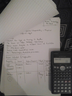
Here the result from my own experiment of LDR by using 12V battery


SCHEMITT TRIGGER

the Schemitt trigger only use a couple transistor as a switch. but in this project i just try two transistor only


Friday, September 7, 2012

WEEK 6

with 
BISMILLAHIRRAHMANIRRAHIM


INTRODUCTION

In this weeks, im doing some study about the circuit of the project and understand as well. By this, i will more understand about how the circuit work. This is methods is needed the knowledge what had i already study from semester 1 till now; from the basic of principles of the components to the components give an effect to the circuit (combination of the circuit).


UNDERSTAND THE MAIN CHARACTERISTIC


In this circuit, there were four of the main characteristic and one the main component

              • Comparator
              • Monostable
              • Schmitt Trigger
              • Astable
              • LDR (component)


1.0 FOR MAIN CHARACTERISTIC DESCRIPTION 


1.1 Comparator

Use LDR resistance and 4k7 ohm as voltage divider for Tripping voltage (at negative)
For the Reference voltage(at positive), it used a permanent resistor (not adjustable)
V1 > V2, Vo=1
V1< V2,  Vo=0


1.2 Monostable 

Monostable is giving a stable state for a certain time only.
It receive input from comparator at leg 6 for IC 7556.
Monostable circuit is function to avoid the light system is off for a moment when a sudden light coming


1.3 Schemitt Trigger

Circuit has fast change over one state to others state.
In this project we used  1 transistor to produce  this effect. And the second one is an emitter follower.
The circuit will drive to turn on the light

1.4 Astable 

Act as clock pulse for IC 4017. An Astable circuit produces a 'square waves' , this is digital waveform with sharp transition between (0v) and high (+vs). this circuit is not stable at any state. the output continue to changing from low to high


2.0 LDR DESCRIPTION 

LDR is Light Dependant Resistor. Output is in resistance. Two Cadmium Sulphide photoconductive cell with spectral response similar to that of the human eye.


3.0 PROJECT FLOWCHART

In this project, comparator is used to read data from the LDR (sensor) and control the either only LED1 or both LEDS will be switch on. Where in the real thing, the LED1 is assumed as car light system while LED2 is assumed as car’s high beam. Figure shows how the system work


Sunday, September 2, 2012

WEEK 5

with
BISMILLAHIRRAHMANNIRRAHIM


INTRODUCTION

Being engineering for the future, he or she should understand what is the main purpose of the project was build for and its related to the current situations. Thus, the project and knowledge is not a waste after it done and ready to apply or sold. 

As my supervisor advised to me to look and search about the current of car light technologies and the effect of its.


RESEARCH & STUDY THE SITUATION

1.0 PROBLEM STATEMENT


Traffic accidents in Malaysia have been increasing at the average rate of 9.7% per annum over the last three (3) decades (Figure 1). Compared to the earlier days, total number of road accidents had increased from 24,581 cases in 1974 to 328,264 cases in 2005, reaching more than 135% increase of accident cases over 30 years. The number of fatalities (death within 30 days after accident) also increased but at slower rate compared to total road accident from 2,303 in 1974 to 6,200 in 2005. However the upward trend of fatalities dropped in 1997 after Malaysia Government established a 5-year national road safety target to reduce road accident deaths by 30% by the year 2000. 


2.0 SURVEY


The survey is about to know the current situation in car technologies in Malaysia. The location survey is around Selayang, Selangor at buyong wokshop. the survey was taken about 10 minutes to complete the questioner


2.1 SURVEY RESULT


The most popular car’ brand in workshop for major and minor repair cause of accident per month in table 1


And what is the purpose of survey is taken for this project?

Because of the technologies inside those car are not same., such the engine system, hydraulic system and light system. and the light system will be focus on.


3.0 EXAMPLE OF LIGHT NEEDED ALERT

This is the example of car sensor system from Gentex company (Automotive product) for controlling car beam

camera sensor at back mirror


the operation of beam controller from Gentex company


when facing others car at front side

camera is detect light intensity

opposite car was passing by

high beam is maintain when no car is coming forward


Thursday, August 23, 2012

WEEK 4

with
BISMILLAHHIRRAHMANIRRAHIM


THE EID DAY


It's like a happy day for Muslims people because one month to fight the desire to eat and drink from sunrise to sunset.At this time its give some time to rest for brainstorm for the project. 

And

 with this opportunity i would like to ask your forgiveness especially to my supervisor if my attitude is harmed your feeling due i being your student

And i would like to ask forgiveness to all my friends and all the reader too 


Wednesday, August 15, 2012

WEEK 3

with
BISMILLAHHIRRAHMANIRRAHIM 


INTRODUCTION

In this week, i did a simple thing but its the key of this project to be success. This is the part where the circuit  will construct in step by step and to make the project plan going smooth as the plan is. Thus, i take all part of this project and separated them as what i need to do first till the last end.

CIRCUIT PLANING OF THE DEVELOPMENT


           THE FLOW CHART SHOW HOW CIRCUIT DEVELOPMENT


The design process is divided into seven stages.
    • In initial stage, system design- where to understand how the systems work (requirements )
    • In the system design, the program can be more simple and easy to understand) 
    • The next stage is about to input output assignment- to divide the input and output where to give more easily for designing the circuit. 
    • Third stage is circuit design; the design is modeled by Proteus 7.3 (windows base). After run and simulated the program, the calculation is needed. 
    • The calculation is to recheck the system work as the specification needed.  The second last stage is monitoring the program after calculation. 
    • The oscillator or trainer board can be used to monitoring the program’s function. 
    • Circuit construction is last stage where the prototype model is build and ready to apply. 


Saturday, August 11, 2012

WEEK 2

with
BISMILLAHHIRRAHMANIRRAHIM


INTRODUCTION

In this week I meet Madam Julie Roslita bte Rosli at her office at Electronics Section. She is my supervisor for Final Year Project. Then, we discuss about problem that related to choose the logbook or blog. Here i would like share about my supervisor who she is and what she good at


MEET THE SUPERVISOR

She more prefer to use the blog and update the blog every week until Engineering Day. But for myself, i more prefer to use log book because its easy to do as reference as all note i gather in the paper/book.

Thus, for i just made two things, a note/log book and a blog at the same times.


MY LOG BOOK

my log book is function to take a note from magazine in larger in size like either in magazine or in website (print out) or in previous FYP, then refer to my supervisor to take some advice


my logbook
inside my logbook 

MY NOTE 

for my note, i used to take a short note and idea from all source, such as friends, senior, the saller (at jalan pasar)

outside my note

inside my note


MY SUPERVISOR IS


My supervisor is Madam Julie Rosita Bte Rosli. She is in electronic section at level 5 in Unikl BMI. She clearly good in electronic knowledge. She used be my lecturer for two semester. she tough me about principles of electronic and digital electronic.


Education :


M.Sc in Electronic Eng (UPM)
B.Eng (Electrical / Electronic) University of Lincoln
Higher National Diploma (BTEC)
 .

Specialization :

Electronic

 Embedded System, Microprocessor,  Microcontroller, Interfacing, FPGA and SOC


Thursday, August 2, 2012

WEEK 1

with
BISMILLAHHIRRAHMANIRRAHIM


INTRODUCTION

This the time when the knowledge is applied as BMI motto is. As final year student, the project is needed to do by his/her own and guided by the supervisor. For me, my supervisor is Madam Julie Roslita Bte Rosli at level 5. She is in electronic section and really good in electronic knowledge as she already be my lecturer once upon a time ago. About her, will be explain in the next upcoming update of this blog  

THE SOURCES

By the briefing from FYP committeemen  the diploma students need to do the project from the magazine at rps.bmi.edu.my. Students need to choose one of the title from the magazine and needed supervisor to approve it. 

Thus, i choose from Everyday Practical Electronic volume 3 issue 11 at pages 792-796.

Then the project of mine just begun as below


INTRODUCTION OF THE PROJECT

Light needed alert is automatic switch on and off depending on the light falling to the sensor (LDR). It can be set to respond in reasonably bright condition or in dim light. It can be adapted to work either way round, switching on when the light gets brighter, or when it become dimmer. 


OBJECTIVES

The main objective of this project is to develop the automated car's light brightness system controller which can control the brightness of car light when there is a car on the opposite direction approaching toward.


SCOPE AND LIMITATIONS

The scope of this project is use to detect two behavior of light source (for driving situation), first, surrounding (by environment) eg: day night, raining day etc
For the limitation, this system is developed in the main road only especially in the highway


PROJECT BLOCK DIAGRAM AND DESRIPTION


Block diagram


PROJECT DESCRIPTION


Ignition/source    : As power source for the circuit
Switch                    : The wire which connect from ignition to circuit
IC (CA3130E)         : A comparator to compare voltage tripping voltage
                                     with reference voltage
LDR                          : A sensor to detect the light
Light System          :Car’s light system